Desktop Lathe
Overview
I worked with a team of 4 other students to design and fabricate a manual desktop lathe. The lathe is rated for aluminum and meets functional requirements based on the user persona of an RC hobbyist.
In a test of accuracy and material removal rate, our lathe performed the best in both categories among the six student-designed lathes. The lathe also survived tests simulating a spindle crash and a drop from desktop height.

Contributions
I worked on this project in a team of 5 students for an MIT class (2.72 Elements of Mechanical Design).
My contributions included:
-
Modeling overall thermal and mechanical behavior
-
Designing CAD (Solidworks) for the spindle
-
Selecting bearings and other parts according to desired specifications
-
Fabricating components including spindle shaft, carriage skirts, flexures
-
Measuring lathe stiffness, accuracy, and repeatability
Skills
modeling | machining (manual and CNC) | Solidworks | MathCAD | measurement | waterjet
Functional Requirements
We determined functional requirements (FRs) for our lathe based on our intended user, an RC hobbyist. Key functional requirements for the overall lathe are listed below:

We set specific functional requirements for each of the subsystems we designed (spindle, x-axis cross slide, z-axis drive) in addition to the overall lathe FRs. The lathe is also designed to survive a fall from desktop height and a crash impulse to the spindle to account for potential accidents during use. The lathe is manually controlled and designed to cut aluminum.
Modeling and Design
Before fabricating the lathe, we modeled each subsystem to ensure it would meet the functional requirements.
We started by modeling the spindle. We decided to use tapered roller bearings with spring washers to ensure that the spindle shaft would be properly constrained while allowing for thermal expansion. To model the forces experienced by the bearings and shaft, we drew free-body diagrams and created a spreadsheet to parametrically model the system. We also created a thermal circuit model to predict the thermal behavior of the spindle to account for expansion and overheating.

Spindle layout with tapered roller bearings arranged so that spindle shaft is constrained but allowed to expand to prevent thermal runaway.
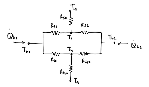
Example thermal circuit model of spindle shaft. Heat generation rate in bearings is calculated based on equation from bearing catalog, depending on factors including bearing force and rotational speed.
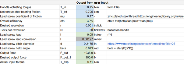
For the x- and z-axis drives, we modeled the lead screws consider-ing friction, handle actuating torque, resolution, and travel speed. We again used a parametric model in a spreadsheet, a part of which is shown in the image here.
In terms of design choices, we used a dovetail mechanism with a cantilevered lead screw for the x-axis drive and potted rail bushings with flexures for the z-axis drive to exactly constrain each mechanism.
The stiffness of the lathe was a critical functional requirement, so we modeled the stiffness of compliant components as well as the overall stiffness of the lathe. For example, we used a Hertzian contact model to estimate the stiffness of the set screw contacts on the gib (thin copper piece to adjust the stiffness of the dovetail). We also modeled the stiffness of the flexures using finite element analysis (FEA), and we used a bolted joint model to calculate the force-displacement relationship for the z-axis lead screw.
For the overall stiffness of the lathe, we created a homogeneous transformation matrix (HTM) model in MathCAD. The model calculates the overall displacement between two points of interest in response to an input force by tracing the force propagation path throughout the structural loop. The structural loops for the x- and z-axes are shown below.


Structural loops showing path of force propagation in the x- (left) and z- (right) axes. These structural loops are used in the HTM model to calculate overall stiffness of the lathe.

Example translation and rotation matrices used for HTM model in MathCAD.
The HTM model allowed us to predict the displacement of the end of a part based on our predicted cutting forces, ensuring that our design was able to achieve the desired radial and axial accuracy when cutting.
Fabrication
The parts I contributed to fabricating include:
-
spindle shaft (CNC lathe)
-
spindle housing cap (waterjet, manual mill)
-
motor mounts (waterjet)
-
carriage skirts (manual mill)
-
dancing man and rail flexures (waterjet)
-
tool holder (manual mill)

We faced some challenges while fabricating certain components of the lathe. For example, the spindle shaft required tight tolerances (<0.001") to ensure a proper interference fit with the bearing, so we had to carefully measure and adjust the turning operation on the CNC lathe to achieve the desired tolerances. Another challenge was making small and thick parts on the waterjet. We made sure to design the flexures to account for the waterjet kerf, added tabs to prevent small parts from falling into the machine, and improvised fixturing techniques when using small stock material.
In some cases, we also ran into issues when there were discrepancies between CAD and actual parts due to using imported parts. Notably, the height of the spindle relative to the carriage was much lower than we had intended, so we redesigned the tool holder to extend beyond the side of the carriage to allow enough clearance for the chuck.


Testing
We ran several experiments and measurements to verify that our lathe met all functional requirements. The most critical FRs (repeatability, accuracy, and stiffness) were measured to be well within the target range, as shown in the table below.

Lathe met all functional requirements. Accuracy and repeatability measurements are based on 0.5" diameter, 2" length cylindrical aluminum stock. Uncertainty values are primarily from averaging over multiple trials.

In this setup, two dial indicators are used to measure the runout of the spindle. Measurement tools used for other tests include force gauge, micrometer, and calipers.
For the class, we had a final competition with two parts:
-
Accuracy: turn down the stock diameter to as close to 0.375" as possible within 3 minutes
-
Material removal rate (MRR): machine away the entire volume of material within 1" of the original end of the part
The starting stock for both tests was a 0.5" diameter aluminum cylinder with 0.5" of hex stock at the end. Out of the six teams, our lathe performed the best in both parts of the competition, achieving a diameter within 0.0008" (20 microns) of the target and removing the material in 27 seconds.


Accuracy (left) and material removal rate (right) tests.
The lathe was also required to pass three rigorous tests to verify its robustness:
-
Testing x- and z-axis drives with a person standing on the lathe carriage
-
Hitting the spindle with a sledgehammer to simulate a spindle crash
-
Dropping the lathe from desktop height
Our lathe performed well under all three tests, maintaining smooth actuation during the first test and suffering no noticeable damage from the second and third tests.
Reflections
In addition to building proficiency with tools (e.g., lathe, mill, waterjet, measuring tools), this project emphasized the importance of modeling and testing. Because we were building a precision machine, we had to be especially intentional with our design choices. We set specific, quantitative functional requirements for the lathe and used engineering modeling to ensure that our design would meet the desired standards. We also had to verify that our actual machine performed as expected by using the appropriate measurement tools and experimental setups.

There were a few oversights with measuring externally supplied parts, so if I were to revist this project, I would adjust the design to account for these issues, such as raising the spindle to allow more clearance for the chuck. Also, at the beginning of the project, we spent a lot of time trying to refine our model and fell behind schedule, but we were able to get back on track once we started fabrication. For future projects, I've learned to better integrate and balance the modeling side of engineering with the physical parts and fabrication processes.